Demonstration of the V2 robotic hand showing full finger movement and control.
V3 Robotic Arm and Body
Aluminium Arm Upgrade & Wrist System Design
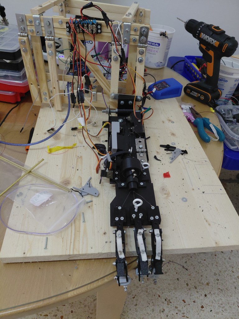
The arm structure was upgraded from wood to aluminium using angle sections and cross members to significantly improve strength and rigidity.
The finger design was refined by integrating tendon guides directly into the 3D printed components, eliminating the need for separate guide pieces that were prone to detachment. A slimmer finger profile enabled the use of M2.5 × 16mm bolts secured with Nyloc nuts.
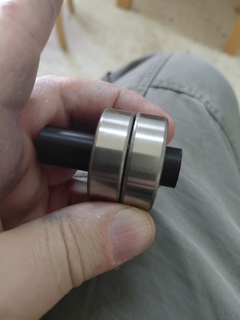
A new wrist system was developed using 6202-2RSH/C3 bearings (15mm inner diameter, 22mm outer diameter), housing a central 3D printed shaft for tendon routing.
At the elbow joint, 608 bearings (8mm inner diameter, 22mm outer diameter) were used, mounted on 8mm bolts to provide smooth rotational movement.
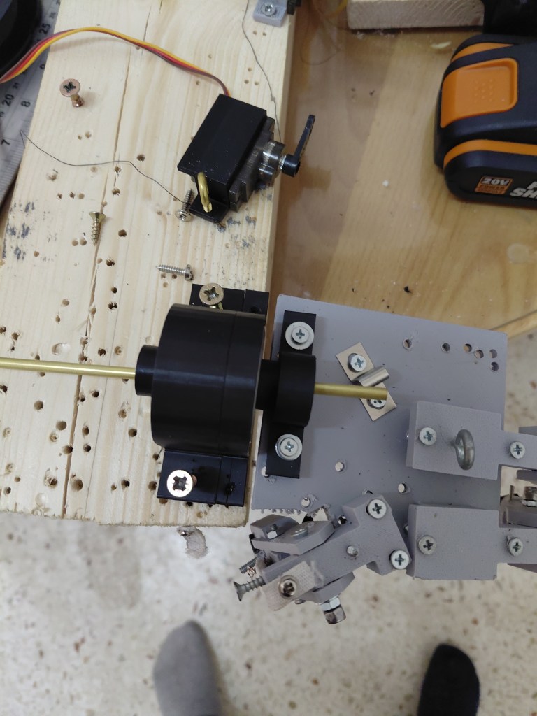
These upgrades improved mechanical reliability, alignment, and overall motion control of the arm.
Body Framework for Robotic Arm Mounting
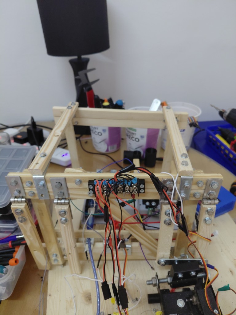
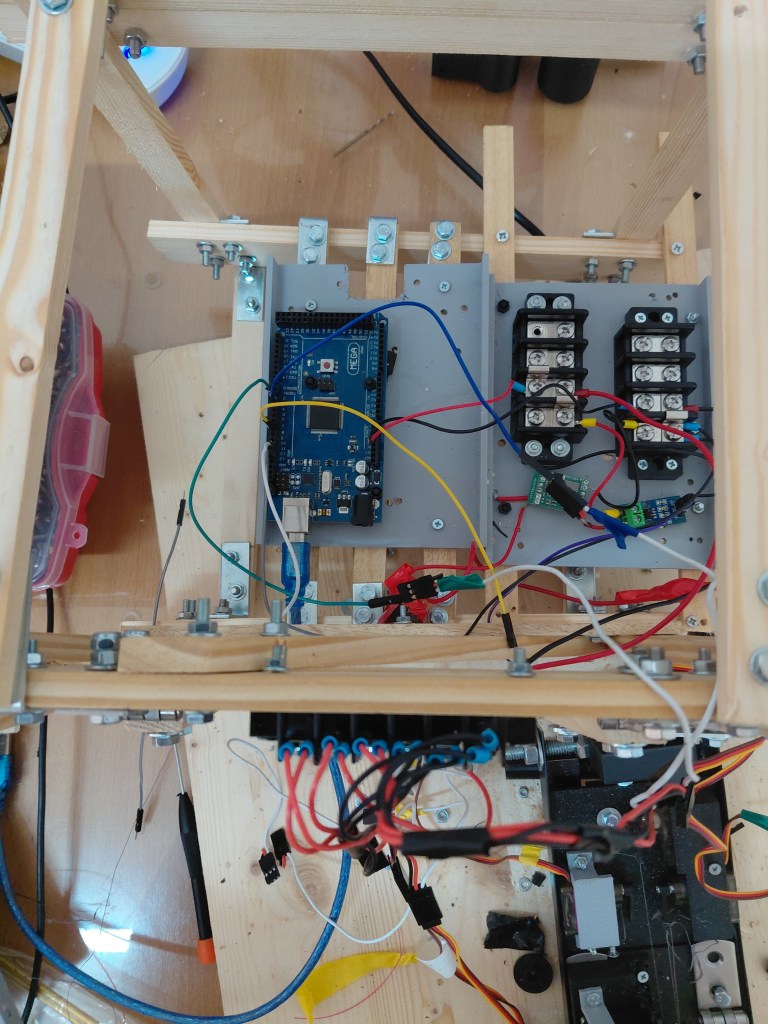
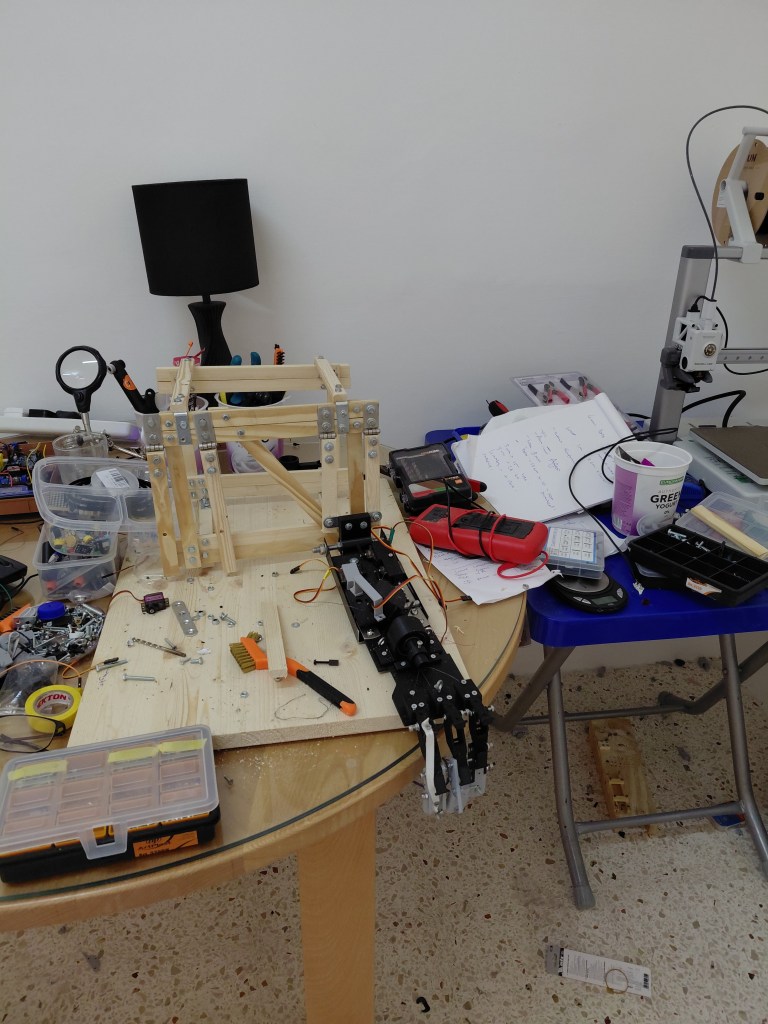
A structural frame was constructed using 10mm × 20mm pinewood lengths, combined with steel hinges and bolts to create a stable mounting platform for the robotic arm.
Hinges and a temporary upper support were added to prototype elbow joint movement. The Arduino Uno and power system were relocated to the base to reduce load on the arm and minimise the torque required by the servos.
The main 30A-rated power distribution was split into separate positive and negative rails to improve safety and wiring clarity.
A secondary 20A distribution point was mounted at the top centre of the frame, allowing easy access for servo extension connections.
This layout improved overall system balance and reduced mechanical strain on the arm during operation
Testing the Robot Arm
The following tests demonstrate precision grip and object-handling capabilities of the robotic hand.
Coin Pickup Test
Achieving reliable coin pickup required precise positioning of the forefinger and thumb. Multiple iterations were tested before consistent success.
Grip Strength Test
V2 3d Printed Arm
Mechanical Design and 3D Printing.
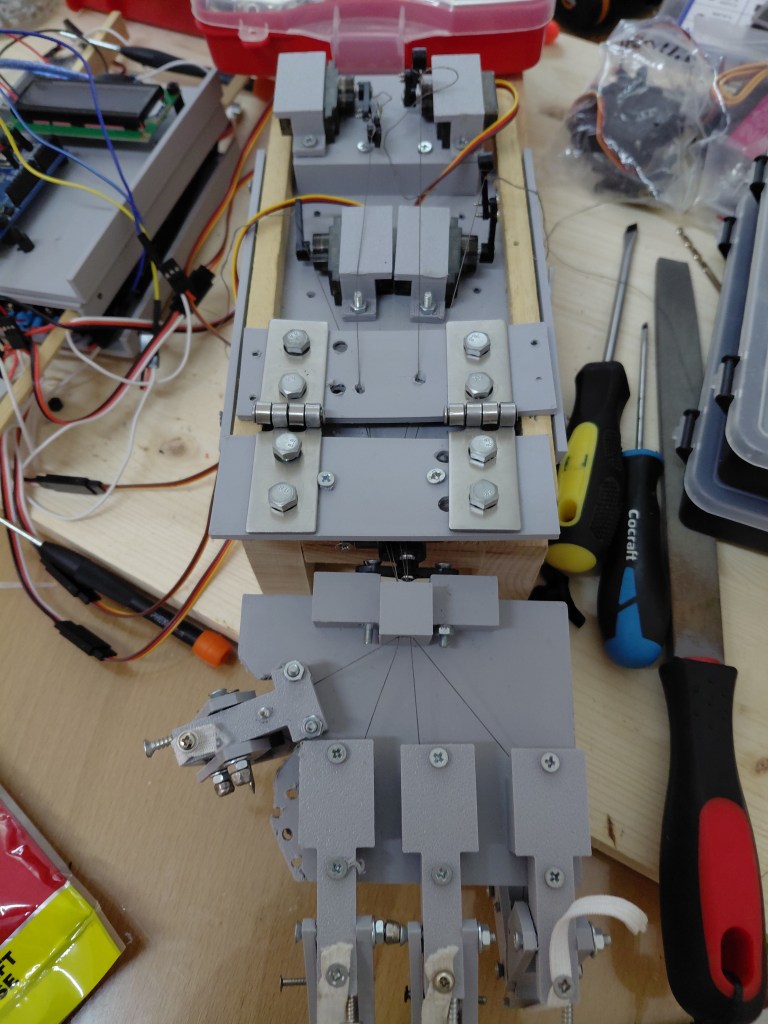
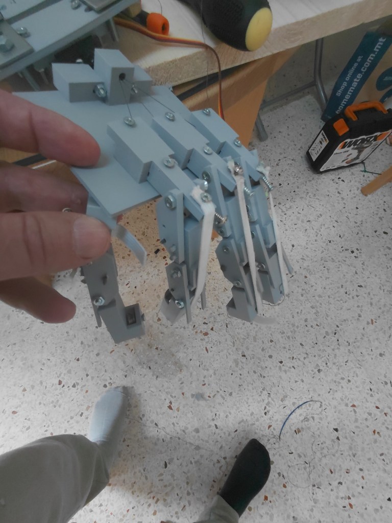
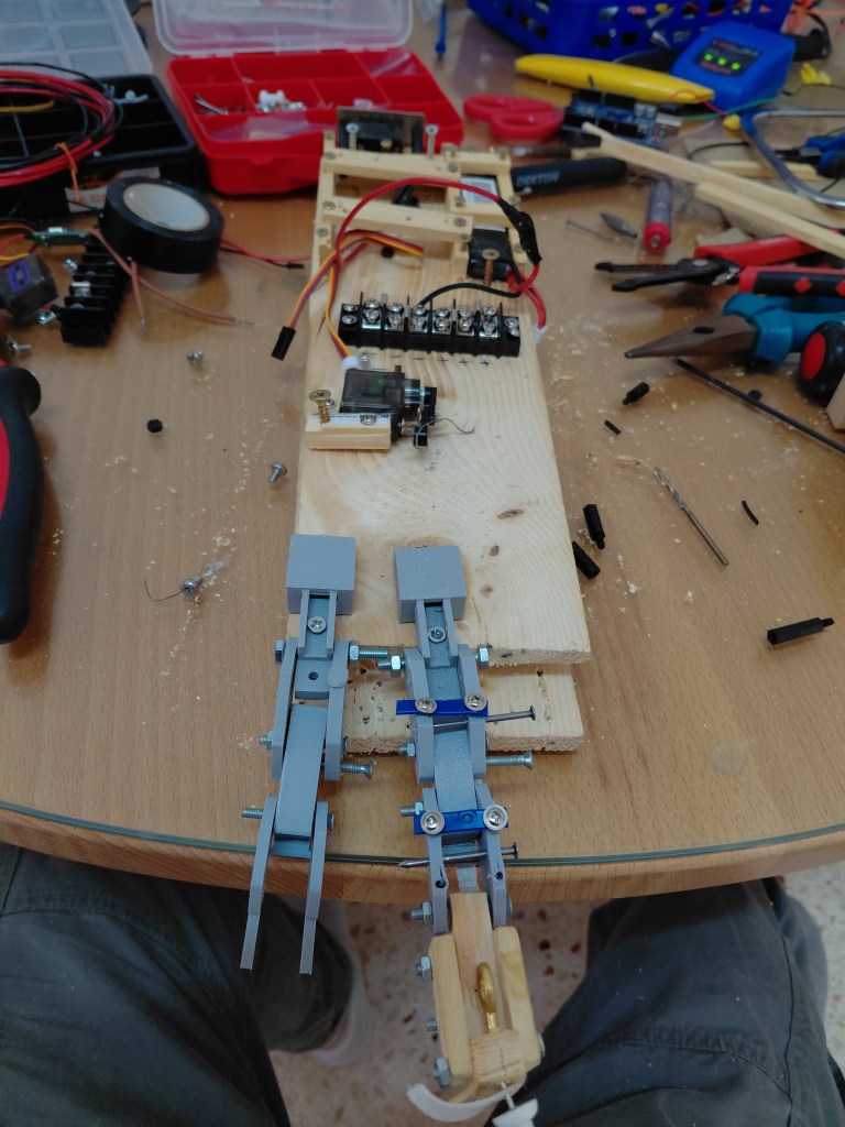
3D printed arm with wooden support beams.
Arduino Uno used as the main control board.
Elastic added to provide passive return force, reducing the need for continuous servo actuation.
Transition to 3D printing significantly improved precision and repeatability compared to wood-based prototypes.
Design focused on simplifying mechanical control while maintaining functional finger movement
Power System Design
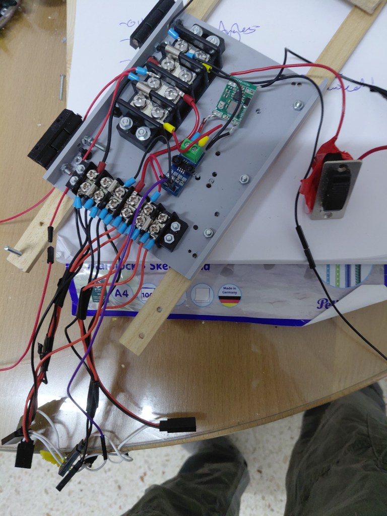
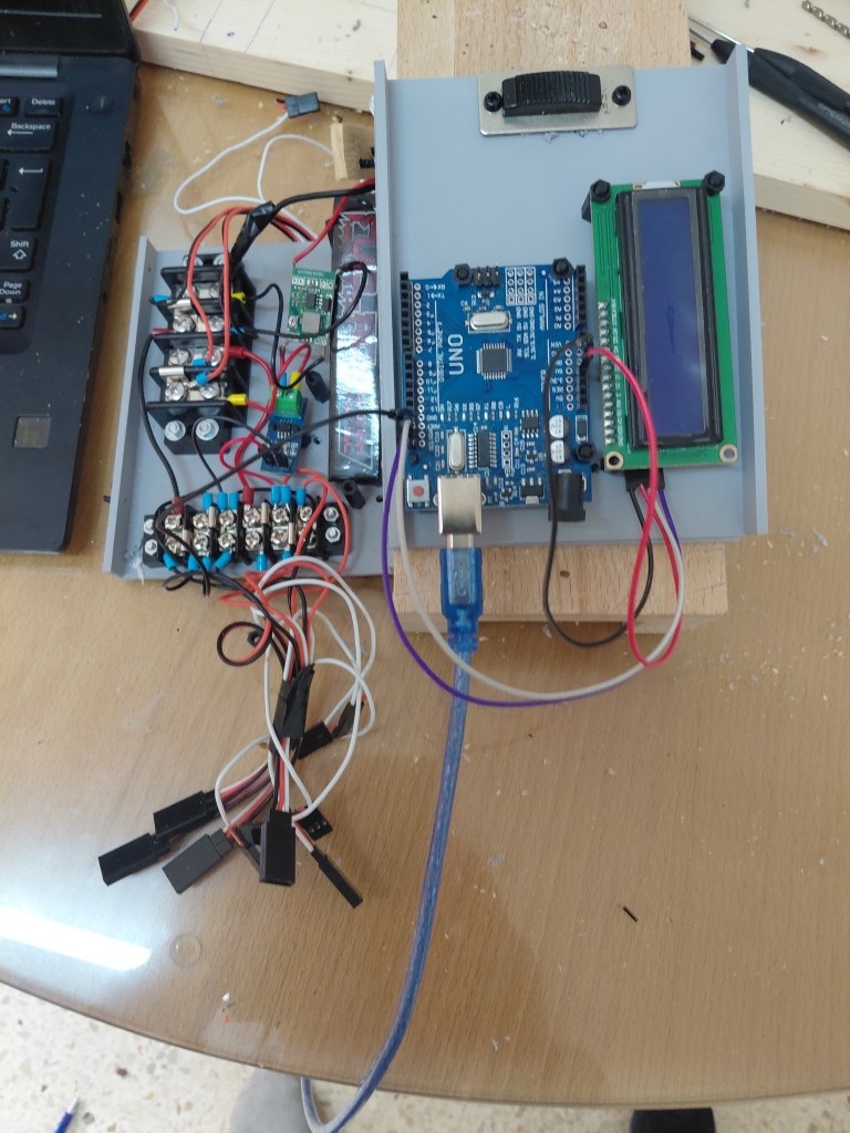
Power supply setup includes a capacitor and a buck converter stepping voltage down from 7.4V to 5V
Power distribution is rated at 30A at the main distribution point, with a separate 20A distribution rail dedicated to servo power.
Haitronic Current Sensor Module added for monitoring current on the LCD.
Ferrules used for improved power connections.
Always remembering the common ground!
System designed to simplify power distribution for servos while maintaining safety through high-current-rated components.
V1 Wood Finger Development
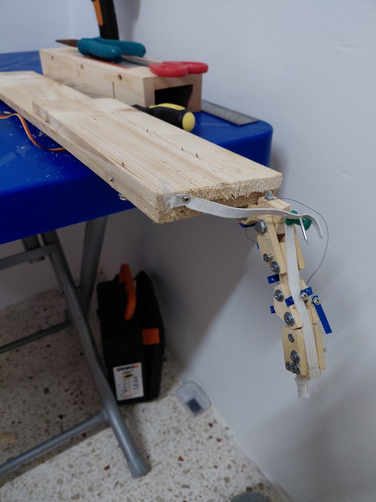
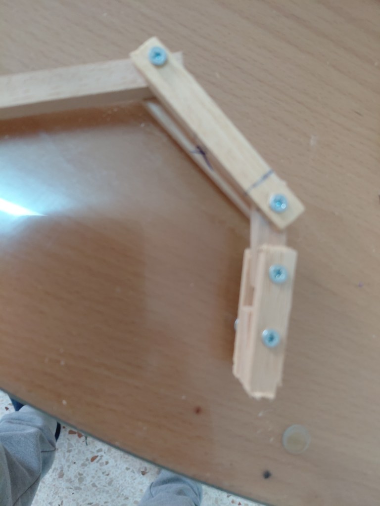
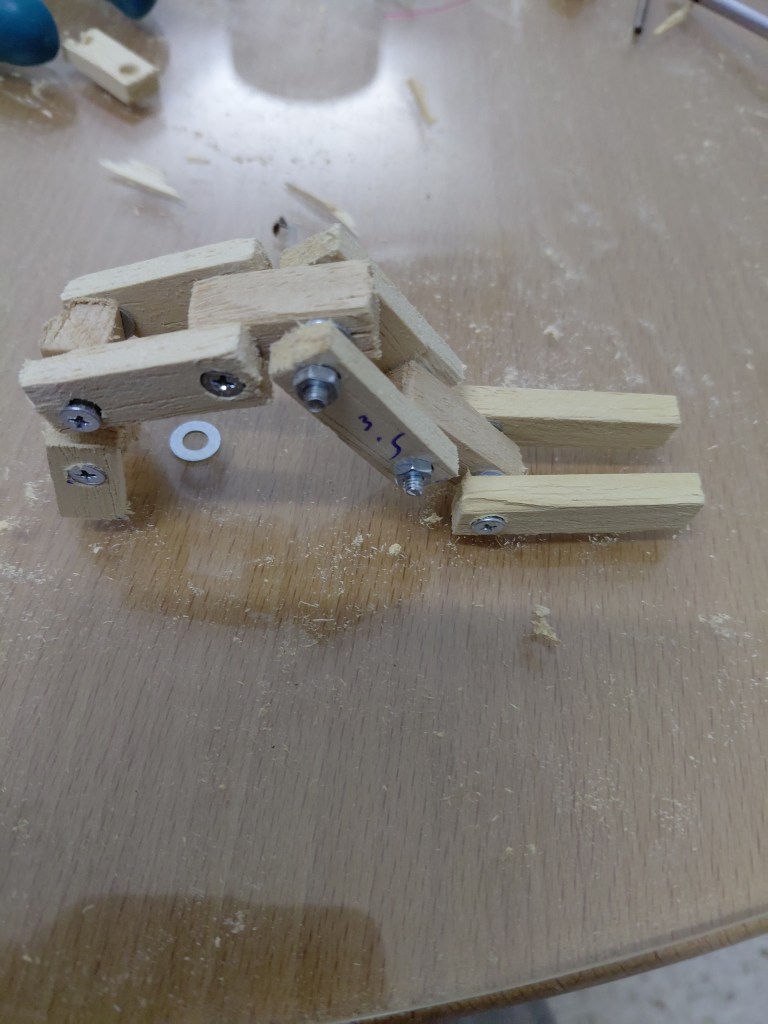
Early experimentation focused on developing a functional finger mechanism using wood prototypes.
Geometry proved critical, with guide placement significantly affecting the ability to achieve a natural grasping motion.
Iteration at this stage highlighted the importance of alignment and linkage geometry in achieving controlled finger movement.
Early Learning Essentials
Robotic Crane Kit Testing
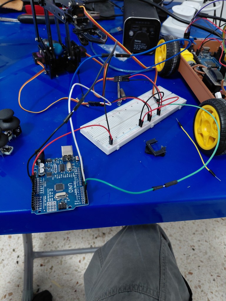
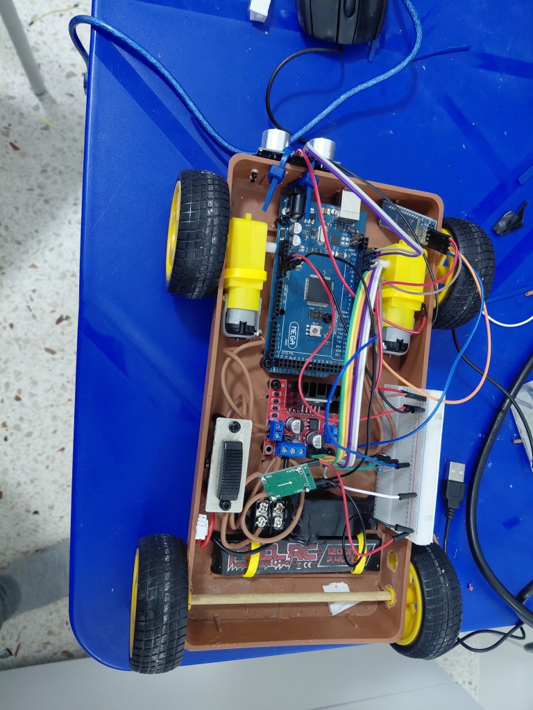
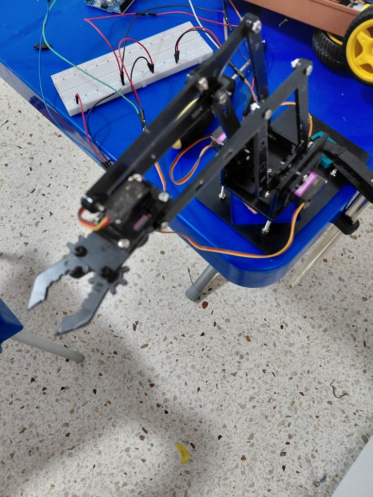
Early learning focused on developing core electronics and control skills through small robotics projects.
A mobile robot platform was built using DC motors, powered by a 7.4V battery with a buck converter and controlled by an Arduino Mega. A front-mounted motion sensor was implemented to detect obstacles and stop the vehicle.
A robotic crane kit was also assembled, providing hands-on experience with servo control and basic robotic movement, forming the foundation for the robotic arm project.

